Basically a software radio experiment without having to spend lots of money on radio hardware.
These programs implement a low power radio transmitter. All countries have regulations regarding use of radio transmitters. It may very well be illegal to use these programs where you live. Make sure to check the laws in your country before running any of these programs.
Although modern computers and monitors should have no problem dealing with the signals generated or the very unusual X configurations used there might still be a chance that something breaks. You use these programs at your own risk.
This is not for everyone. You need a good understanding of C programming, the X window system and a basic understanding of electronics for these programs to be of any use to you.
sox program.1
VGA cards have high speed DACs4that are used to generate the video signal sent to the monitor. These DACs basically convert the image into an analog signal line by line that is fed into the monitor. This allows us to create a radio signal, display it as an image and have the card convert it to a radio signal for us.
This all sounds good in theory, however reality isn't quite as cooperative as one would wish and there are some obstacles to overcome.
It is possible to minimize the distortions caused by these signals by making the sync intervals as small as possible. Some cards may even let you turn them off completely. Unfortunately I haven't found any card that lets you do this yet.
To minimize the sync intervals you will need to configure custom modelines for your X server. This also has the side effect that you will not be able have a monitor connected to see what you are doing.5
Some chips let you set this to any frequency you want, and in those cases there is no problem! Just set it to 73MHz and use the first harmonic to get to the FM band. Or if your computer is fast enough, try setting it to 220MHz and set the programs to directly synthesize the correct FM carrier.
Some chips can only set their pixel clock in certain increments. For these chips you will need to find a dot clock between 73MHz and 87MHz that the card accepts and then use the first harmonic to transmit on the FM band.
In general, if ![]() is our dot-clock frequency and
is our dot-clock frequency and ![]() is the
carrier frequency then the harmonics will appear at
is the
carrier frequency then the harmonics will appear at ![]() for
all integer values of
for
all integer values of ![]() .
.
So, if you have a dot-clock frequency of 73MHz and a carrier frequency of 35MHz then the first harmonic will end up at 73 + 35 = 108MHz which is right at the top of the FM band.
Just remember that the dot-clock frequency meeds to be at least twice that of the carrier due to the sampling theorem.
The Intel card in my laptop lets me activate the VGA port using the
xrandr command, and will hapily send a signal out of it as long
as my laptop monitor is active. Fortunately it also lets me set the
VGA port parameters independently from the LCD parameters so this
works out fine.
Another Intel card I had in my workstation wasn't so kind. The driver even refused to let X start unless I had a monitor connected. In the end I was forced to patch the driver so it always thinks the monitor is connected.
xrandr and have
your laptop monitor active.
Next, you need to select a dot-clock frequency.
Now you are ready to configure the VGA port. You should try to configure it to use the minimal possible sync intervals. Below are two examples of how this can be done.
xrandr --newmode RadioDAC 73 1152 1152 1152 1153 864 864 864 865
xrandr --addmode VGA RadioDAC
xrandr --output VGA --mode RadioDAC
The first command sets up a new modeline7, the first parameter is the dot-clock, the second is the width of the display, third is the start of the horizontal sync, fourth is the end of the sync and the fifth parameter is the total width including sync pulse. The next four parameters are the same thing but for the vertical dimension.
The HTOTAL value in the above example is 1153, which is the lowest that I could set on my card and still get a signal out of it. This causes us to loose about a pixel to the horizontal sync, which isn't that bad.
The VTOTAL value is also just one more than the height of the display. Unfortunately this causes us to loose an entire scanline and will certainly cause some signal distortion. I have not found any way around this.
The commands for this configuration are the same as the previous, with the only difference being the larger resolution.
xrandr --newmode RadioDAC 73 2048 2048 2048 2049 2048 2048 2048 2049
xrandr --addmode VGA RadioDAC
xrandr --output VGA --mode RadioDAC
FM radio transmitters modulate a carrier in the frequency range of 87.5-108MHz with a baseband audio signal that has a 15kHz bandwidth. The frequency shift is 75kHz, so the transmitted signal frequency varies between 75kHz below the carrier frequency to 75kHz above the carrier frequency.
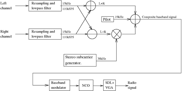
For stereo FM transmission the modulation itself remains the same, but the baseband signal is no longer a simple audio signal. It is instead a composite of the 15kHz mono audio (Left + Right channel), a 19kHz pilot signal and a 15kHz difference signal (Left - Right channel) modulated using DSB-SC on a 38kHz subcarrier. This composite signal is then frequency modulated as for the mono case. The result is that the signal is fully compatible with old mono receivers.
For more information on FM broadcasts see [6]
This processing is done using the sox program in a separate
thread so we don't have to do it ourselves.
The modulator first converts the sample from signed 16bit integers to
a real valued sample in the range [-1,1] and then calculates the
frequency used to represent this sample in the radio signal according
to the formula below:
The reason this is done at this point is because of the lower sampling rate of the baseband signal, this leaves more processor power over when the real radio signal is generated.
In these particular programs the NCO also implements a very simple interpolation filter and upsampler so it can accept a 30kHz baseband signal to modulate a carrier at a significantly higher sample rate.
This oscillator operates at the dot-clock frequency, and must be very fast for the CPU to be able to cope.
The output of this block are the samples of the radio signal, which in this particular case are the pixel lightness values in the ``image''.
For stereo modulation we need a higher baseband sampling rate to accomodate the stereo pilot and subcarrier, so the signal is resampled to 110kHz instead of 30kHz.
Like in the mono modulator sox is used for this block.
The modulator also creates a difference signal that the receiver will use to reconstruct the left and right channel. This is the L-R signal in the figure.
The resulting sample is then scaled by a constant so that it is within [-1,1] before being sent to the baseband modulator.
No parameters are accepted by this program. To change the parameters
of the generated signal the #defines at the beginning of sig1.c
must be changed and the program recompiled.
If you want to understand how these programs work then this is the obvious place to start.
monofm program implements the mono modulator described in
section 5.1.
The program accepts the following parameters:
An example invocation:
./monofm -r 73000000 -c 35000000 -w2048 -h2048 -f tst.mp3
stereofm implements the stereo modulator described in
section 5.2.
It accepts the same parameters as monofm.
An example invocation:
./stereofm -r 73000000 -c 35000000 -w2048 -h2048 -f tst.mp3
monofm and stereofm programs.
Use the modulator description in section 5 as a
functional reference.
The programs are written to be fast so they can be used in real time. Because of this the source is not always readable and is not really a good example of how to write well structured C programs. Please keep this in mind when checking out the source.
The dds in dds1.h uses a linear interpolation to approximate
sample values that fall in between entries in the lookup table giving
it slightly better precision compared to dds2.h that just
returns the value closest to the phase of the signal.
However the generator in dds2.h is faster.
fmdds.h extends the generator in dds2.h by adding a
slope factor that skews the frequency a bit after every sample.
This is useful since the generator is fed with a baseband signal at a
significantly lower sample rate. The slope acts as a very efficient
and quite good low-pass interpolation filter.
baseband_mod. It runs in it's own thread so as to take
advantage of multicore CPUs.
The baseband modulator opens a pipe to sox and receives samples
that it converts to a frequency and slope.
These parameters are stored in two ring buffers freqbuf and
slopebuf that are read by the NCO when generating the radio signal.
baseband_mod
function.
First a sample from both the left and right channels is read from the
pipe to sox. Then the sum and difference signals are calculated
and a composite sample is created. This sample is then converted into
a frequency and slope which are saved in the ring buffers.
modulate_sample which is the
one that actually does the baseband modulation and stuffing of samples
into ring buffers.
It also contains the function fmsignal which reads the ring
buffers and creates the actual radio signal. The function loops over
the pixels and lines of a VGA frame and calculates the sample value
(pixel lightness) for each sample in the radio signal. It reads the
frequency and slope information from the ring buffers when it needs it
during signal generation.
When the frame is finished it waits the apropriate amount of time and then instructs the VGA card to display it. After that it starts generating the next frame.
This function runs in its own thread.
Q:Why?!?
A:Why not?
Q:What distortions can I expect due to the sync intervals?
A:The horizontal sync intervals are so short, and so high in frequency that you shouldn't hear them. They will probably cause some HF distortion in the radio wave though.
The vertical sync intervals are a bigger problem. They will cause static or humming with the same frequency as the framerate. Unfortunately this is usually very audible.
Q:Can you disable the sync intervals entirely?
A:I don't know. I haven't managed it yet. If you succeed please email me how you did it and what VGA card you used.
Q:Why are there no mutexes to avoid problems with the ring buffers?
A:Because they are not needed.
The thread writing data to the ring buffers is much faster than the thread that reads the data. So it only needs to fill the buffer up when the signal generator has consumed data, and then when the buffer is full it just waits a while for more data to be consumed.
This document was generated using the LaTeX2HTML translator Version 2002-2-1 (1.71)
Copyright © 1993, 1994, 1995, 1996,
Nikos Drakos,
Computer Based Learning Unit, University of Leeds.
Copyright © 1997, 1998, 1999,
Ross Moore,
Mathematics Department, Macquarie University, Sydney.
The command line arguments were:
latex2html -dir ../html -local_icons -html_version 4.0 -white -show_section_numbers -split 0 -link 2 vgasig.tex
The translation was initiated by Bartek on 2009-04-19